Simulation of Plasma Breakdown in a Low Pressure rf Plasma
H.B. Smith, D. Vender and R.W. Boswell
Space Plasma Group, Plasma Research Laboratory, RSPhysSE,
The Australian National University, ACT 0200, ACT, Australia
A 1D particle-in-cell (PIC) simulation has been used to study the breakdown and evolution of an argon plasma. Analytic equations modelling the density evolution during and after breakdown have been developed from the simulation results.
1. Introduction
Many aspects of plasma breakdown and formation in rf systems are still only poorly understood. This paper presents results from a particle-in-cell (PIC) simulation of plasma breakdown and the approach to steady state in a low pressure, capacitive, rf argon plasma. The PIC results are explained using a simple analytic model.
2. Simulation
Breakdown is modelled from a low starting density (103 cm-3) using a 1D PIC code with spherical electrodes. The inner electrode is coupled through a capacitor to the rf generator, and the outer electrode is grounded. The source voltage has an exponential rise time to empirically model the effect of a matching network. The model uses the conditions: Vrf (pk-pk) = 500V with a rise time of 2 ms; frf = 13.6 MHz, C = 0.1 nF, pressure = 50 mTorr and the inner and outer electrode radii are 2.5 and 7.5 cm.
3. Results
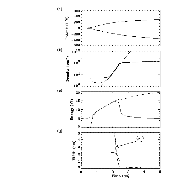
Figure 1 shows the evolution of the electrode voltage Velec, the ion ni and electron ne densities, the average electron energy ke and the sheath width at the powered electrode sl, after the source voltage is applied. Initially the density is very low so the electric fields can strongly penetrate the plasma. For the first 0.5 ms Velec = 0 and there is no change in either electron density or temperature, but as the applied voltage increases the electron energy increases proportionately (see Figure 1(c)). At first the average energy is still too low to produce substantial ionisation and so loss rates exceed creation rates, and the electron density decreases. Once the electron energy reaches a critical value (~10 eV) an ionisation avalanche commences, producing an extremely rapid increase in the density.

Fig 1. Evolution of (a) Velec
(b) ni (solid) and ne (dash-dot) with the analytic model (dotted)
(c) ke (solid line) with scaled Velec (dotted)
(d) sl and debye length (dotted)
This density rise can be analytically described by considering the particle balance
in the system

where n(t) is the plasma density, vi the ionisation rate per electron, u the average particle velocity at the walls, Aw the wall area and V the volume of the reactor. The first term denotes creation of particles due to ionisation and the second loss rates to the walls. During the breakdown phase ions are essentially immobile since they cannot respond to the rapidly changing fields, and so only electron losses need to be considered. Assuming that the electrons have a Maxwellian distribution, then the ionisation rate per electron can be approximated by:

where Nn is the neutral density, kTe is the electron temperature, Eion=15.7 eV, qo=10^(-16) m^2 and u the average electron velocity =
 .
Equation (1) therefore depends on both electron temperature and density. Assuming
that the dependance on temperature is small, so that the <kTe> can be used in place
of kTe(t), then equation (1) can be integrated to give
where b = vi - u and n(to) is an integration constant. For <kTe>=12 eV b=14.2 s^-1, and using n(to)=10^3 cm^-3, equation (2) is plotted in comparison with the density in Figure 1(b), giving a good fit to the simulation results.
As the density approaches 10^8 cm^-3 the debye length approaches the system length. At this stage a sheath forms at the live electrode (see Figure 1(d)), and starts to shield electrons from the oscillating field, so the electron temperature drops rapidly to its steady-state value of 3eV.
After the plasma has broken down the density rises much more slowly, since only electrons in the vicinity of the moving sheath edge can be heated. Thus only a small fraction of the electron population is capable of ionising, and the simulation shows that ionisation rate becomes approximately constant. Equation (1) can therefore be written in the form

where I is the steady-state ionisation rate and ub is the bohm velocity (losses to the walls are controlled by the ion flux). Integrating (3) gives

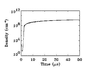
where ns is the steady-state density, and C = 1.2Aw ub/V, which is the time required for an ion at the centre of the plasma to diffuse to the walls. For a 3 eV argon plasma C = 40 us. Using ns = 5.5x10^9 cm^-3 (from the simulation) equation (4) is plotted in comparison to the simulation results in Figure 2.

Fig. 2. Post-breakdown electron density evolution, compared with equation (4) (dotted).
4. Conclusion
During the breakdown the electron density decreases until the average electron energy
reaches 10 eV. After this rapid ionisation occurs and the density increases exponentially.
Once the density becomes large enough sheaths can form and the electron temperature drops to 3 eV. The density then increases in proportion to an inverse exponential
until it reaches a steady state value.