Charging of the Blocking Capacitor in a Pulsed Asymmetric Reactor
C.Charles, H.B.Smith and R.W.Boswell
Space Plasma Group, Plasma Research Laboratory, RSPhysSE,
The Australian National University, ACT 0200, Australia
A spherical 1D particle-in-cell (PIC) computer simulation and small experimental plasma reactor, have been used to investigate the effects of pulsing a low pressure, capacitive, rf argon plasma. We show that the charging rate of the blocking capacitor in the match box is determined by the ambipolar drift of ions to the earthed electrode. Following plasma breakdown there is a net current flow in the system which charges the blocking capacitor. Both the PIC results and the experimental measurements show that the current flow is produced by a delay in the onset of the electron current to the earthed electrode, which is clearly correlated to the charging time of the capacitor. During this period, the PIC simulation shows that the plasma potential in the centre of the discharge is higher than one would expect, preventing electrons from reaching the earthed electrode.
1. Introduction
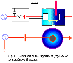
Pulsed plasmas have recently shown great potential for material processing applications, and are also of interest for fundamental studies of non-linear plasma phenomena, such as breakdown. The time scales are important, especially when using short pulse lengths (~ms). This paper studies a low pressure, capacitive, rf, argon plasma in asymmetric reactor geometry. Figure 1 shows both experimental and simulation setups. The PIC code models a reactor with concentric spherical electrodes, with the inner electrode connected to the rf generator through the blocking capacitor. Results are presented for the first few ms after the pulse is applied. This time covers the transition from a "symmetric" to an "asymmetric" discharge as the blocking capacitor charges and a bias voltage develops. To study this transition experimentally 1ms-on/10ms-off pulses were used, in order to obtain low particle densities at the end of the post-discharge period.

2. Results
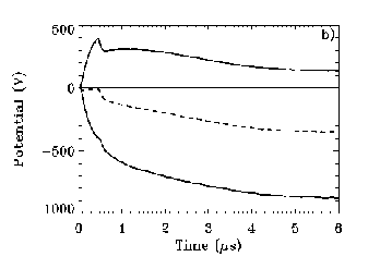
The evolution of the voltage on the live electrode in both experiment and simulation
is shown in Fig. 2. At about 500 ns there is a discontinuity (shown prominently in
the simulation results). This marks the end of the breakdown phase, at which time
the Debye length enters the system and sheaths form at the electrodes. At this point,
the electrode voltage is symmetric and still increasing. As the blocking capacitor
starts to charge, a bias voltage develops and the electrode voltage becomes increasingly
asymmetric. The bias voltage reaches its maximum value at 3.5 ms for the experiment and 4.5 ms for the simulation.


Fig. 2: Voltage form on the powered electrode from the expt (top) and the simulation (bottom)
A Langmuir probe was used to measure the ion and electron fluxes at various positions
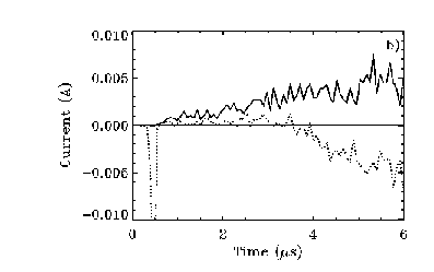
along the main axis of the experiment. Figure 3 shows typical results from both experiment
and simulation for currents at the the grounded electrode. The ion current starts at approximately 0.5 s, just after the plasma has broken down, while for both
experiment and simulation a delay of ~3.5 s in the arrival of the electron flux
is observed. Although it was not possible to experimentally measure the currents at the powered
electrode, simulation results show that during the first 3.5 ms there is a negative current to the powered electrode. During this time, therefore,
a net current flows in the system, which acts to charge the blocking capacitor.


Fig. 3: Ion (positive) and electron (negative) currents at the grounded electrode from the expt (top) and the simulation (bottom)
There must be some mechanism which keeps electrons from reaching the grounded electrode
in order to produce the net current flow. Results from the simulation (Fig. 4) show
that this is accomplished by a large positive jump in the plasma potential immediately after breakdown. Figure 4 shows that during the time in question the potential
in the plasma is always much larger than zero, so electrons are prevented from approaching
the grounded electrode. The ion current to the earthed electrode is balanced by the electrons which reach the powered electrode once during each rf cycle, when the
voltage on the electrode reaches its maximum and the sheath collapses. It is therefore
the ion flux which controls the charging time of the capacitor.

Fig. 4: Evolution of the plasma potential from the simulation
3. Conclusion
Immediately after breakdown a large jump in the plasma potential prevents electrons
from reaching the earthed electrode. This allows a net current to flow in the system,
which acts to charge the blocking capacitor. The charging rate is determined by the
diffusion time of ions to the earthed electrode.